Overlays, Layers, and Shapes
11 minute read
Images can be annotated with Tags, Properties, and Shapes. Shapes are organized into Layers and Overlays, and Overlays can be associated with Images. A Cell can contain multiple Overlays with Layers and Shapes.
|
Tip
|
Images and Overlays with the same name are connected and displayed together, including all the Layers and Shapes within them. |
Shapes, Layers, and Overlays can be managed in the Editor app.
Overlays
|
Note
|
Overlays can be automatically created when adding Shapes to Images. These automatically created Overlays have the same name as the Images and are connected to them. Custom-made Overlays can have any structure, and the connection to the Images is optional and defined by name. |
Create an empty Overlay
-
Left-click on the
Morebutton.
Figure 1. Overlays More options -
Click
Create empty overlay.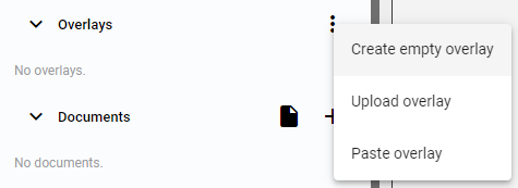 Figure 2. Create an empty overlay
 -
Set the Overlay name and choose the
Searchableoption.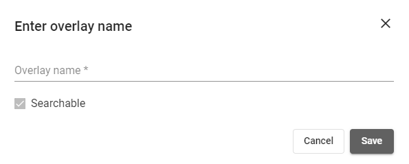 Figure 3. Enter overlay name window
 -
The saved Overlay is added to the list of Overlays. The Overlay contains an empty virtual Layer called
base.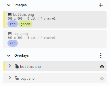 Figure 4. New OverlayNote
Name the Overlay the same as the Image to connect them. Images and Overlays with the same name will be displayed together.
Upload Overlay from disk
-
Left-click on the
Morebutton.
Figure 5. Overlays More options -
Click
Upload overlay.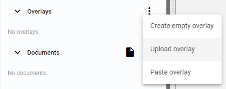 Figure 6. Upload overlay
 -
Select the Overlay to upload and choose the
Searchableoption.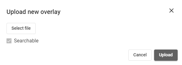 Figure 7. Upload new overlay window
 -
The uploaded Overlay is added to the list of Overlays.
Copy and paste Overlay
|
Note
|
Only one Overlay with the same name can exist in a Cell, so you can copy-paste Overlays between Cells. The copied Overlay includes all non-empty Layers and Shapes, while empty Layers or Overlays without any Shapes are ignored. |
-
Right-click on the Overlay and select the
Copyoption.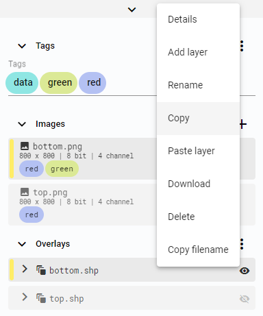 Figure 8. Copy overlay
 -
Go to the Cell where you want to paste the Overlay.
-
Left-click on the
Morebutton.
Figure 9. More options button -
Click
Paste overlay.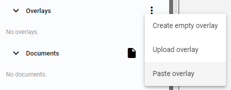 Figure 10. Paste overlay
Overlay details
-
Right-click on the Overlay and select the
Detailsoption.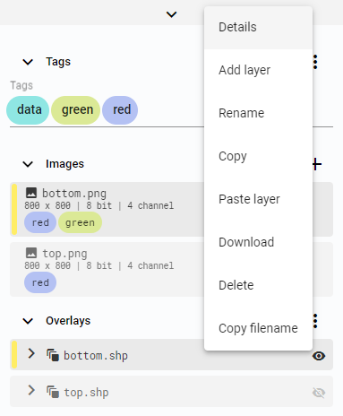 Figure 11. Overlay options
 -
The Overlay details contain information about the Overlay, its Tags, and Properties.
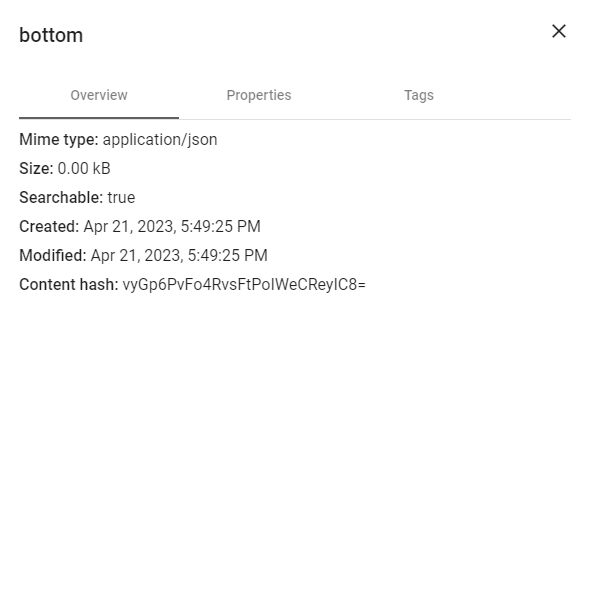 Figure 12. Overlay details
Rename Overlay
-
Right-click on the Overlay and select the
Renameoption.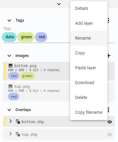 Figure 13. Rename Overlay
 -
Set the new Overlay name.
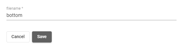 Figure 14. Set filename
Download Overlay
-
Right-click on the Overlay and select the
Downloadoption.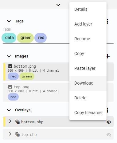 Figure 15. Download Overlay
The downloaded Overlay is a text file describing the Overlay with all its Layers and Shapes in JSON format. The file is named the same as the Overlay.
Copy Overlay name
-
Right-click on the Overlay and select the
Copy filenameoption.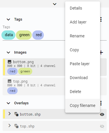 Figure 16. Copy filename
Delete Overlay
-
Right-click on the Overlay and select the
Deleteoption.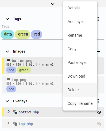 Figure 17. Delete Overlay
Layers
Layers group Shapes within Overlays.
Create Layer
Empty Overlays have one virtual base Layer, which is replaced by the first created Layer.
-
Right-click on the Overlay and select the
Add layeroption.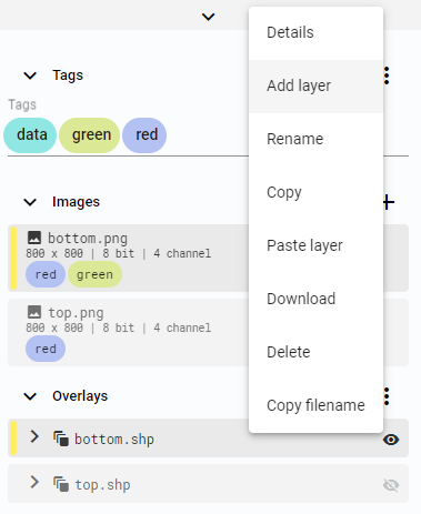 Figure 18. Add layer
 -
Set the Layer name.
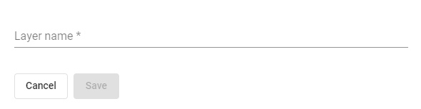 Figure 19. Enter layer name
|
Note
|
If the Overlay contains only an empty base Layer, it will be replaced by the new one.
|
Copy and paste Layer
-
Right-click on the Layer and select the
Copyoption.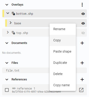 Figure 20. Copy layer
 -
Right-click on the Overlay and select the
Paste layeroption.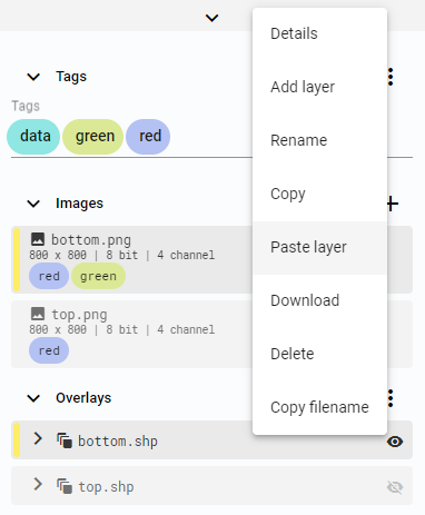 Figure 21. Paste layer
 -
Save the new Layer by pressing
CTRL + Sor clicking theSave changesbutton on the Shape panel.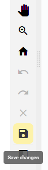 Figure 22. Save button
The Layer can be pasted into an Overlay that already has a Layer with the same name. The new Layer’s name will be extended with (copy).
Duplicate
-
Right-click on the Layer and select the
Duplicateoption.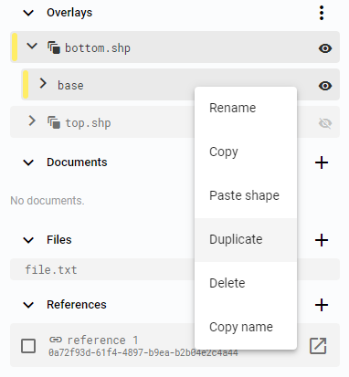 Figure 23. Duplicate layer
 -
Set the new Layer name in the popup window.
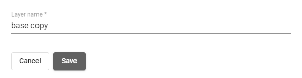 Figure 24. Set Layer name
Rename Layer
-
Right-click on the Layer and select the
Renameoption.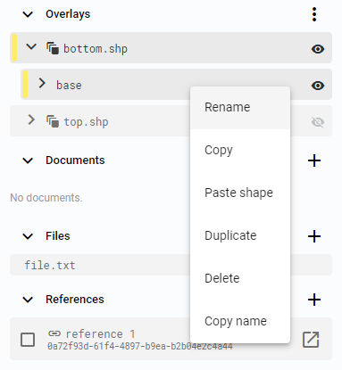 Figure 25. Rename layer
 -
Set the new Layer name in the popup window.
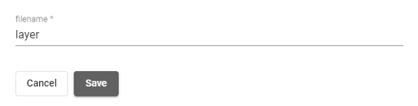 Figure 26. Set Layer name
Copy Layer name
-
Right-click on the Layer and select the
Copy nameoption.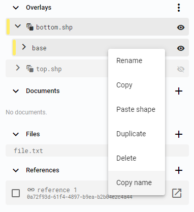 Figure 27. Copy Layer name
Delete layer
-
Right-click on the Layer and select the
Deleteoption.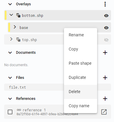 Figure 28. Delete Layer
Overlays and Layers visibility
Each Layer and Overlay can be manually enabled or disabled for any Image in the Cell. The Eye symbol associated with the Layer enables or disables the Layer for the active View. The same symbol associated with the Overlay enables or disables all Layers in the Overlay.
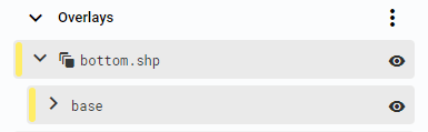
Figure 29. Overlay and Layer enabled
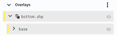
Figure 30. Overlay and Layer disabled
|
Tip
|
Layers and Overlays can be displayed on Images other than the ones they originally belong to. |
Shapes
The annotation panel provides options to create various types of Shapes. Either create the Shapes manually or use one of the available smart tools.
Create Shape
The process to create a Shape is the same for all types, only the Shape definition differs.
-
Select an Image in a Cell.
-
Shapes always belong to a Layer and Overlay. Select the appropriate ones, or they will be automatically created if an Overlay with the same name as the Image exists, along with a
baseLayer. -
Select the Shape to create.
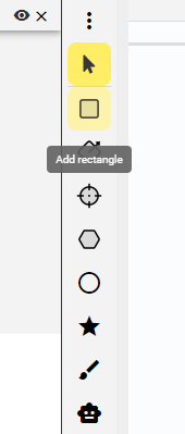 Figure 31. Shape panel
 -
Choose the Shape template.
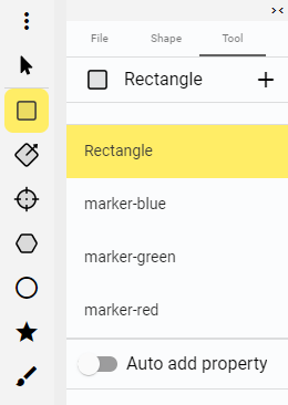 Figure 32. Shape templates
 -
Draw the Shape on the Image.
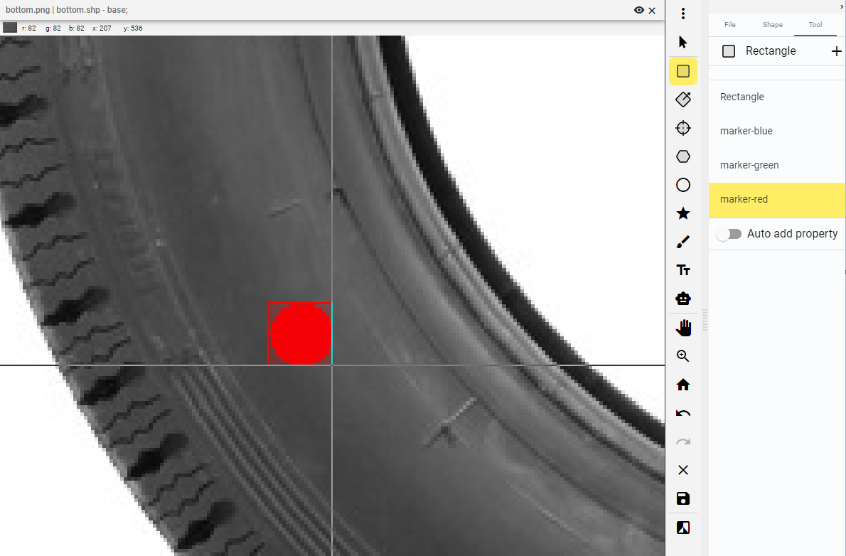 Figure 33. Draw Shape
 -
Save the changes.
Figure 34. Save button
Copy and paste Shape
-
Right-click on the Shape and select the
Copyoption.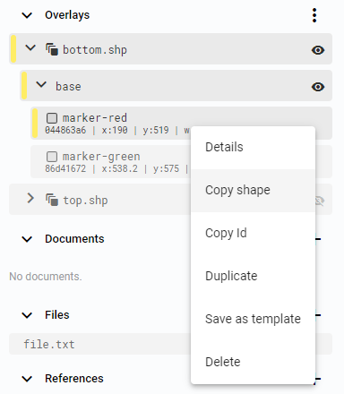 Figure 35. Copy Shape
 -
Right-click on the Layer and select the
Paste Shapeoption.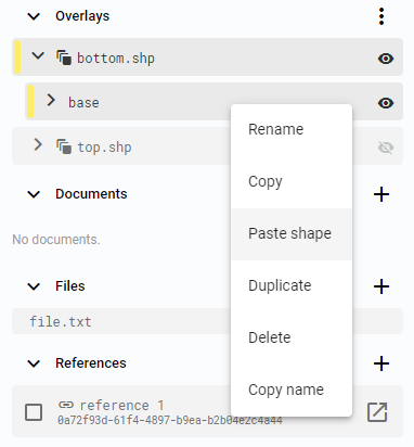 Figure 36. Paste Shape
 -
Save the new Shape by pressing
CTRL + Sor clicking theSave changesbutton on the Shape panel.
Figure 37. Save button
Duplicate
-
Right-click on the Shape and select the
Duplicateoption.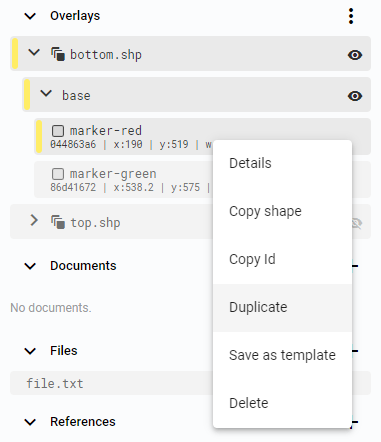 Figure 38. Duplicate Shape
 -
Set the Layer for the Shape copy. It can be the same Layer, another existing Layer from the list, or a new Layer defined by a unique name.
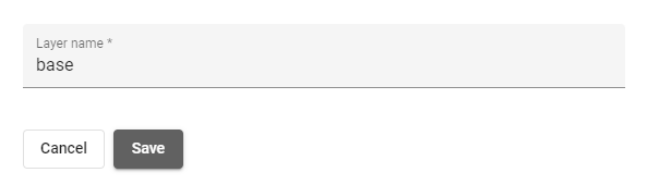 Figure 39. Select Layer
 -
Save the new Shape by pressing
CTRL + Sor clicking theSave changesbutton on the Shape panel.
Figure 40. Save button
Shape Details
-
Right-click on the Shape and select the
Detailsoption.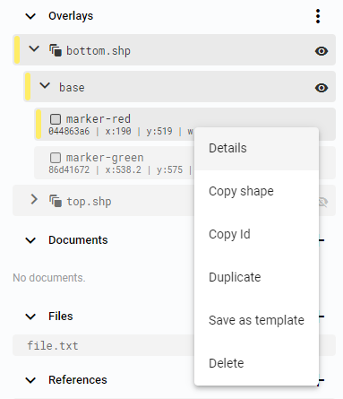 Figure 41. Shape details
 -
The Shape details window provides information about the Shape, including its size, position, color, and Properties. All these parameters can be changed.
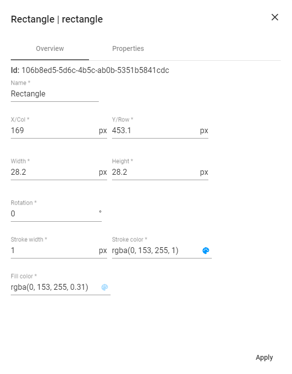 Figure 42. Shape details window
Save as template
Each Workspace has a default set of Shape templates, one for each supported shape type. These templates can be managed in the Workspace settings, and new ones can be created in the Editor app. Different Shape templates can be used to add more information to annotations. Each template also has a default color setting.
-
Right-click on the Shape and select the
Save as templateoption.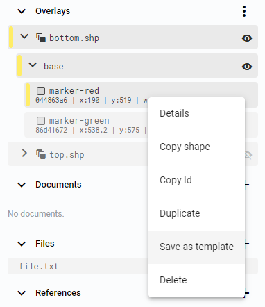 Figure 43. Save as a template
 -
Set the Shape template name.
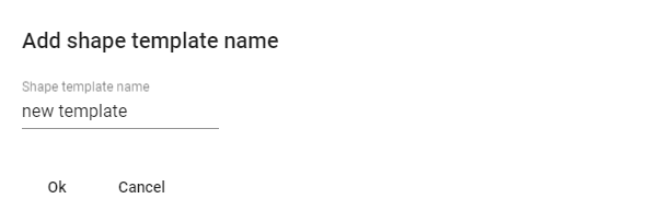 Figure 44. Set Shape template name
Delete Shape
-
Right-click on the Shape and select the
Deleteoption.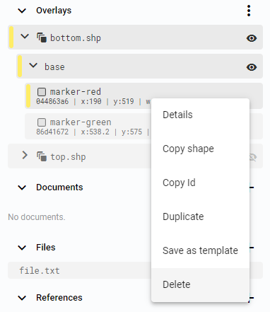 Figure 45. Delete Shape
Shape types
Supported shape types include rectangles, oriented rectangles, crosses, polygons, ellipses, paths, and masks. The mask shape can be created manually or computed with the Smart tool. All shapes, except for the Mask, are described as vectors, while the Mask is described as a raster.
Rectangle
A Rectangle is defined by one point, width, and height. It can be rotated by changing the rotation value in the Shape details.
Add rectangle
-
Click the
Add rectanglebutton.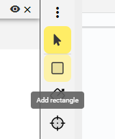 Figure 46. Add rectangle button
 -
First left-click to mark the first point.
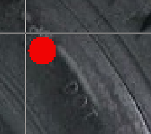 Figure 47. First point
 -
Keep the button pressed and move the cursor to define the rectangle Shape. Release the button to mark the second point.
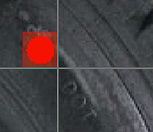 Figure 48. Last point
Oriented rectangle
An Oriented rectangle is defined by one rotated edge and height.
Add oriented rectangle
-
Click the
Add oriented rectanglebutton.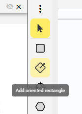 Figure 49. Add oriented rectangle button
 -
First left-click to mark the first point.
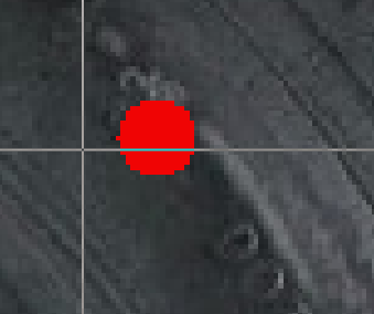 Figure 50. First point
 -
Keep the button pressed and move the cursor to define the angle of one edge of the Shape. Release the button to mark the second point.
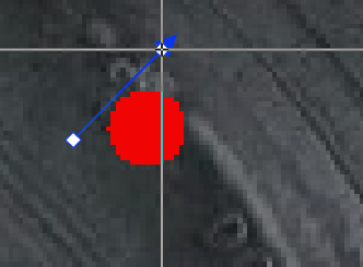 Figure 51. Angle
 -
Move the cursor to define the width of the oriented rectangle and left-click to select the point on the closing edge.
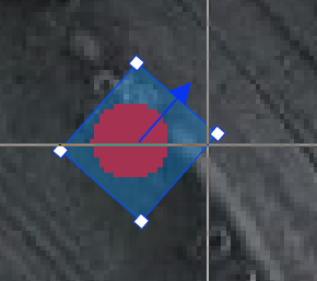 Figure 52. Width
Cross
A Cross marks a single point, and its visual style can be customized.
Add cross
-
Click the
Add crossbutton.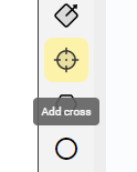 Figure 53. Add cross button
 -
Select the Shape template.
-
Left-click on the Image to define the cross Shape.
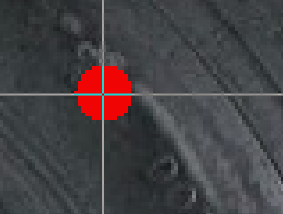 Figure 54. Create cross
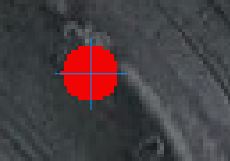 Figure 55. Cross
Polygon
A Polygon consists of a minimum of 3 points. If a Polygon is created with fewer than 3 points, it will not be saved. Points can be added to the Polygon as it is being created. An existing Polygon can be edited by adding points to the closest edge, removing points, or moving them.
Add polygon
-
Click the
Add polygonbutton.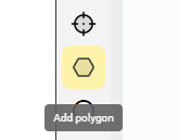 Figure 56. Add polygon button
 -
Select the Shape template.
-
Left-click to mark each point on the Polygon Shape.
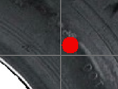 Figure 57. First point
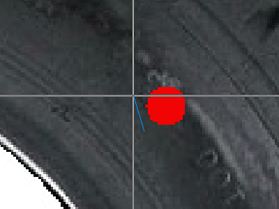 Figure 58. Second point
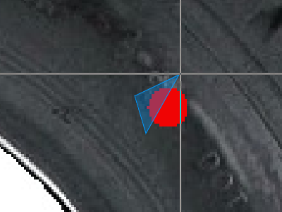 Figure 59. Third point
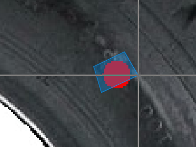 Figure 60. Fourth point
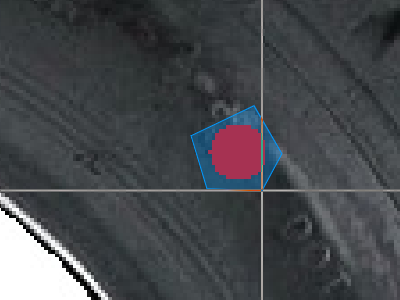 Figure 61. Fifth point
 -
Right-click to finish the polygon Shape.
Ellipse
An Ellipse is created within a rectangle. Rotation can be set after the ellipse is created.
Add ellipse
-
Click the
Add ellipsebutton. Figure 62. Add ellipse button
 -
First left-click to mark the first point.
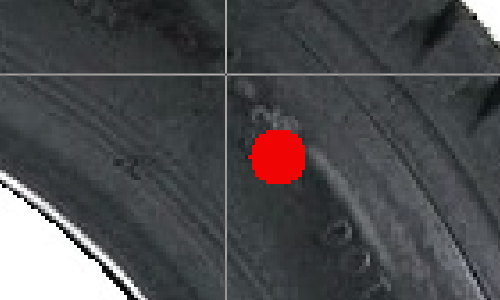 Figure 63. First point
 -
Keep the button pressed and move the cursor to define the ellipse Shape. Release the button to mark the second point.
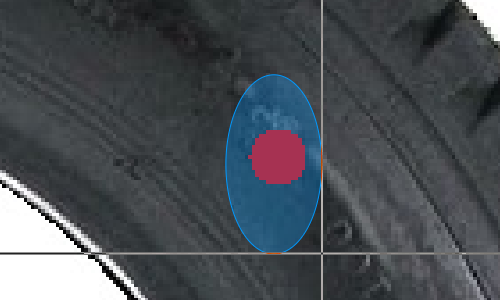 Figure 64. Last point
Path
A Path consists of a minimum of 2 points. The default Path template displays the path with a filled area, which helps with selecting the Shape. To display the path Shape without the filled area, change the Alpha parameter in the color setup.
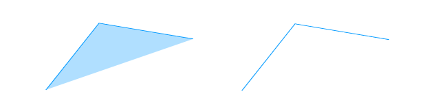
Figure 65. Path
Add path
-
Click the
Add pathbutton. Figure 66. Add path button
 -
Left-click to mark each point on the path Shape.
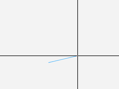 Figure 67. Second point
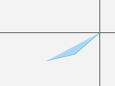 Figure 68. Third point
 -
Right-click to finish the path Shape.
Mask
The Mask does not have any predefined shape. It is created by brush painting. There are various brush modes available, including a simple brush, eraser, brush with automatic area fill, and eraser with automatic area fill. The Mask is saved as a text shape description and an image file that shows the foreground and background.
Add mask
-
Click the
Add maskbutton. Figure 69. Add mask button
 -
Select the brush mode. Options include a simple brush, eraser, brush with automatic area fill, and eraser with automatic area fill.
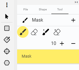 Figure 70. Mask brush options
 -
Move the mouse and keep the left mouse button pressed or left-click to add an area under the cursor.
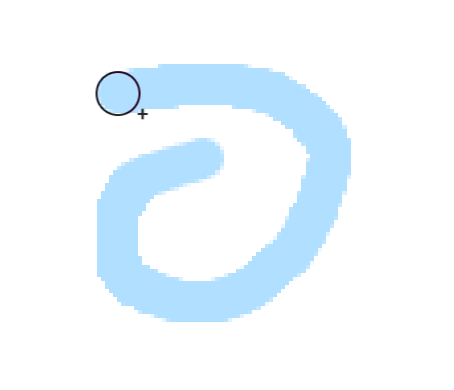 Figure 71. Mask
 -
To erase part of the Mask, Click the
Remove maskbutton..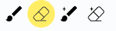 Figure 72. Remove mask button
 -
Move the mouse and keep the left mouse button pressed or left-click to remove an area under the cursor.
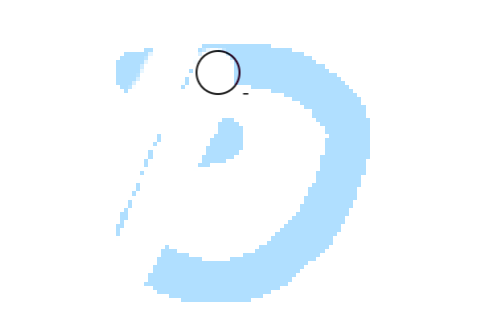 Figure 73. Mask reduced
 -
To add an automatically filled Mask shape click the
AutoFill addbutton. Figure 74. AutoFill add button
 -
Move the mouse and keep the left mouse button pressed to define the mask borders. Release the button to close the mask area, which will be automatically filled.
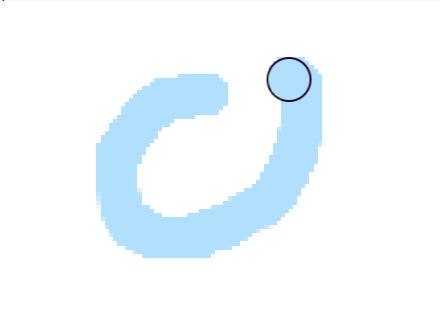 Figure 75. Mask borders
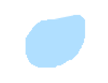 Figure 76. Mask filled
 -
To erase part of the Mask with automatic area fill click the
AutoFill removebutton. Figure 77. AutoFill remove button
 -
Move the mouse and keep the left mouse button pressed to define the mask borders. Release the button to close the mask area, which will be automatically erased.
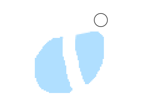 Figure 78. Mask borders
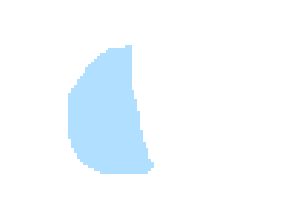 Figure 79. Mask filled
OCR
One of the special functions is OCR detection and recognition. OCR can be used in manual or automatic mode. In manual mode, an oriented rectangle is used as a Shape template, and the expected text needs to be filled in manually. Automatic detection allows selecting a area of the image that is processed automatically by one of the available tools. The detected text is then saved as a Property value.
Add manual OCR
-
Click the
Add OCRbutton.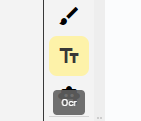 Figure 80. Add Ocr button
 -
Select the Shape template and type. The type can be set to
manualor automatic detection.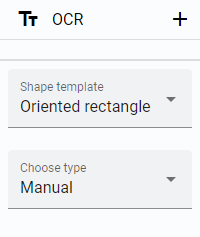 Figure 81. Shape template and type
 -
Draw the Ocr Shape according to the selected Shape template.
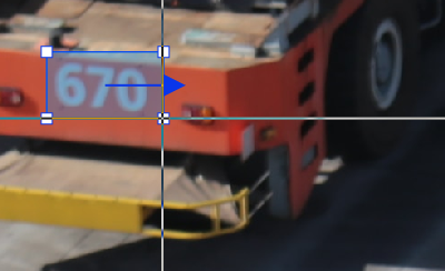 Figure 82. Ocr selected area
 -
If the type is set to
manual, enter the expected text in the prepared Property window.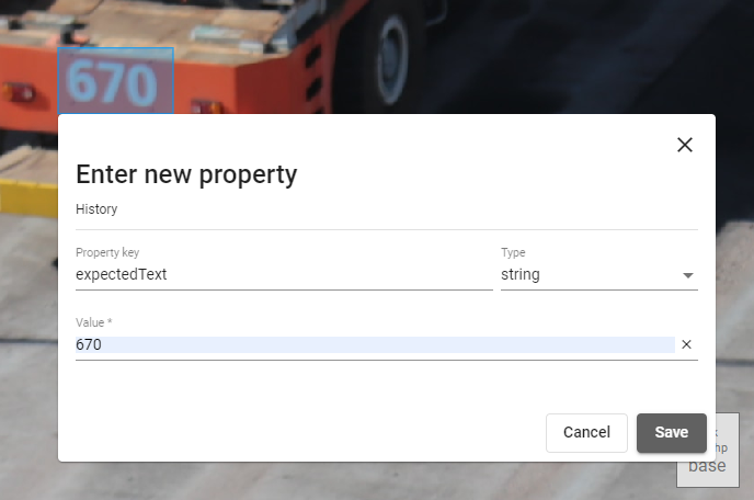 Figure 83. Enter expected text
Add BeeYard OCR
-
Click the
Add OCRbutton.
Figure 84. Add Ocr button -
For automatic text detection, set the type to
BeeYard OCR.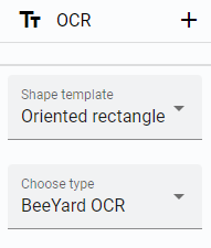 Figure 85. BeeYard OCR type
 -
Select an area for automatic text detection.
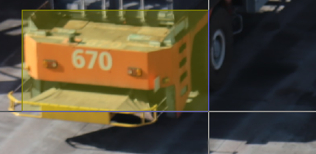 Figure 86. BeeYard OCR area
 -
Allow BeeYard to detect the text in the selected area.
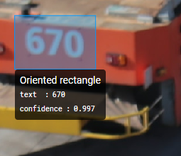 Figure 87. BeeYard OCR detected
The resulting rectangle with the text may be smaller than the originally selected area, or multiple rectangles with the detected text may be displayed.
Smart tool
The Smart tool is used to detect the background and foreground of an Image. The result is a mask that can be edited similarly to the Mask shape.
Use the Smart tool
-
Click the
Smart toolbutton.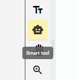 Figure 88. Use Smart tool
 -
Select the desired type.
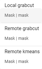 Figure 89. Select type
 -
Select the area for detection.
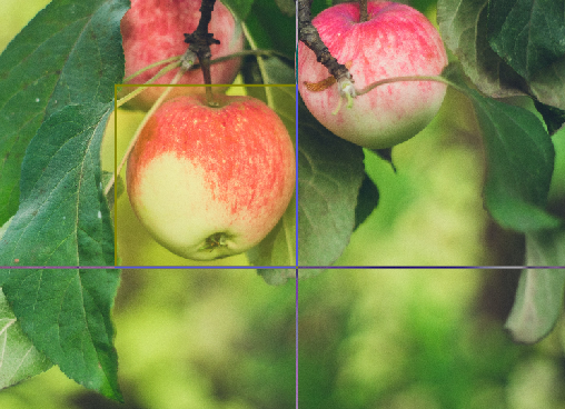 Figure 90. Select area
 -
The Smart tool detects the foreground and background and creates a mask.
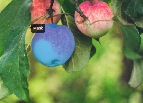 Figure 91. Mask detected